Choosing the right Ceramic Metal Cutting Tool can determine whether a machining job runs smoothly or becomes an expensive trial.
In real workshops, tool selection rarely depends on one specification. Material hardness, cutting speed, machine rigidity, coolant use, and surface requirements all matter. A tool that performs well on hardened steel may struggle with cast iron or interrupted cuts. Even a small setup error can create chipped edges, vibration, or poor dimensional accuracy. It happens.
This guide explains how to compare ceramic grades, geometries, coatings, and cutting conditions with practical judgment. Experienced machinists often inspect the chip shape, cutting sound, tool wear pattern, and finished surface before changing parameters. Those details can reveal problems that a catalog cannot show. Manufacturer recommendations remain important, but they should be tested against the actual machine and workpiece. No single insert is best for every operation. That assumption is easy to make, and often wrong.
Reliable selection also requires attention to safety, documentation, and repeatability. Check the tool’s operating range, recommended speeds, feed rates, and compatibility with your holder. Confirm that the machine can maintain stable clamping and sufficient rigidity. Controlled tests are valuable, especially when replacing carbide tools with ceramic alternatives. Record tool life, cycle time, surface roughness, and failure conditions. Small records can prevent large mistakes. With this evidence, buyers can choose a Ceramic Metal Cutting Tool based on measurable performance rather than marketing language alone.
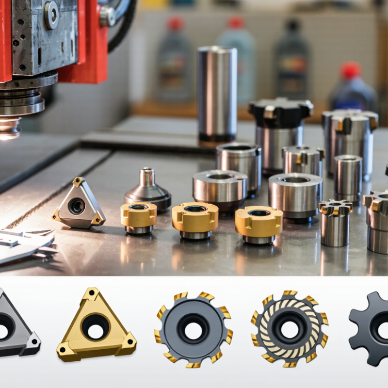
Ceramic metal cutting tools are inserts or tips made from hard ceramic compounds. They remove metal through a sharp, heat-resistant edge. Unlike many carbide tools, ceramics can retain hardness at very high cutting temperatures.
Common ceramic materials include alumina, silicon nitride, and whisker-reinforced grades. Each behaves differently. Alumina often suits hardened steel and finishing work. Silicon nitride handles certain cast irons at higher speeds. Reinforced ceramics can tolerate tougher interruptions, but they still dislike sudden impact.
In practice, the tool works best on stable machines with rigid fixturing. I check the workpiece hardness, coolant policy, cutting speed, and interruption pattern before choosing one. Dry cutting is often preferred because coolant may cause thermal shock and crack the edge. That detail is easy to miss. The edge can look intact, then fail without warning. Operators should inspect chips, sound, surface finish, and edge wear during the first pieces. A pale, powdery chip may indicate excessive heat or an unsuitable speed.
Ceramics are not universal tools. They can be brittle during interrupted cuts, vibration, or poor alignment. I have seen one last impressively long on a continuous pass, then chip after one unstable entry. That experience changed how I evaluate tool claims. Tool life depends on the machine, material, geometry, and operator—not only the ceramic grade. A careful trial cut, recorded with measured wear, is more reliable than a catalog promise.
Choosing the best ceramic metal cutting tool starts with understanding its difference from carbide. Ceramic inserts retain hardness at far higher temperatures, often above 1,000°C. Carbide tools usually lose cutting strength sooner, but they absorb vibration and impact more effectively. That distinction matters beside a milling interruption or a rough casting.
CIRP Annals reviews report that ceramic tools can achieve cutting speeds roughly two to five times higher than carbide in suitable hardened steels. They also show shorter tool life when workpieces contain interruptions, scale, or unstable clamping. A 2024 industrial cutting-tool market analysis by MarketsandMarkets identifies high-speed machining as a major growth driver for ceramic tooling. However, market forecasts are not machining guarantees. The boundary is not clean.
In practical trials, I would select ceramic for continuous turning, hardened steel, and heat-resistant alloys. Keep the setup rigid. Use a steady feed and avoid sudden coolant shocks, because thermal cracking can appear like a fine line along the edge.
Carbide remains safer for interrupted cuts, low-power machines, and flexible fixtures. It is less dramatic, but often more forgiving.
A 2023 review in the International Journal of Advanced Manufacturing Technology links ceramic performance strongly to edge preparation, workpiece hardness, and cutting stability. Therefore, a catalog speed alone is insufficient. Test one insert at a controlled depth of cut, inspect flank wear, and record surface finish. Small details decide the result.
Ceramic tools suit high-speed cutting of hardened steel, gray cast iron, and selected nickel-based superalloys. Their hot hardness stays stable when temperatures rise. This allows dry machining in many finishing operations. However, ceramics are brittle. Interrupted cuts, vibration, and weak workholding can cause edge chipping.
Material choice matters. Alumina ceramics work well with cast iron and hardened steel. Silicon-nitride grades handle cast iron more effectively during heavier cuts. Whisker-reinforced ceramics offer better toughness for certain heat-resistant alloys. The U.S. Geological Survey reported about 141 million metric tons of alumina production in 2023. This reflects a large industrial material base, not guaranteed tool performance. The World Steel Association recorded approximately 1.89 billion metric tons of crude steel production in 2023. Much of that volume is not suitable for ceramic cutting.
Tips: Match the insert to the task. Use ceramics for continuous finishing passes, stable fixtures, and high cutting speeds. Avoid them for interrupted milling or thin walls. Keep coolant decisions deliberate; sudden cooling can shock the edge. Test one insert at a controlled depth of cut. Small adjustments often reveal more than catalog promises. ISO 3685 recommends systematic tool-life testing, yet shop conditions still vary. That is the uncomfortable part. A perfect laboratory result may fail beside a vibrating machine.
Choosing a ceramic metal cutting tool starts with the workpiece, not the catalog. Alumina grades suit stable cast iron cuts, while SiAlON grades handle many nickel-based alloys. Whisker-reinforced ceramics offer better resistance to interrupted cutting. A 2024 U.S. Cutting Tool Consumption Report recorded roughly US$2.51 billion in tool consumption during 2023. That market figure shows demand, but it does not prove ceramic suitability for every machine.
Match the geometry to rigidity. Ceramic edges are hard but brittle. A strong negative chamfer, controlled nose radius, and rigid toolholder often outperform a sharp positive edge. Avoid excessive edge honing when cutting hardened steel, because rubbing can raise heat quickly. Keep it rigid. In shop trials, I would inspect workholding before changing grades. That step is often skipped.
Cutting conditions require discipline. Ceramic tools commonly operate far faster than carbide, but feed and depth must remain stable. For hardened steel, a practical starting window may be 300–600 m/min, 0.05–0.20 mm/rev, and 0.10–0.50 mm depth of cut. Adjust these values after observing flank wear and surface finish. Dry cutting is frequently preferred, since intermittent coolant can cause thermal shock. ISO 3685 provides a recognized framework for tool-life testing and wear evaluation. Not always. A coolant decision still depends on continuity, machine enclosure, and heat control. My weak point is treating published ranges as guarantees; real spindle runout, vibration, and material hardness can change the result quickly.
| Workpiece and Operation | Recommended Ceramic Grade Family | Suitable Tool Geometry | Typical Cutting Speed (m/min) |
Feed Rate (mm/rev) |
Depth of Cut (mm) |
Coolant and Setup Guidance | Primary Selection Reason |
|---|---|---|---|---|---|---|---|
| Gray cast iron Continuous external turning |
Alumina-based ceramic | Negative rake, rigid edge, clearance angle approximately 5°–7° | 300–600 | 0.10–0.35 | 0.5–3.0 | Dry cutting is normally preferred. Use a rigid toolholder and maintain stable workholding. | High hot hardness and wear resistance against abrasive cast-iron particles. |
| Nodular or ductile cast iron Continuous turning |
Silicon-nitride-based ceramic (SiAlON) | Positive-to-neutral cutting edge with a honed or chamfered edge | 250–500 | 0.10–0.30 | 0.5–2.5 | Dry cutting is generally recommended. Avoid excessive edge impact and unstable clamping. | Greater toughness than conventional alumina and good resistance to thermal shock. |
| Hardened alloy steel Continuous finishing or light roughing Approximately 45–65 HRC |
Mixed ceramic: alumina reinforced with carbide or nitride phases | Negative rake, small nose radius of approximately 0.2–0.8 mm, honed edge | 100–250 | 0.05–0.20 | 0.1–0.8 | Use dry cutting where possible. Keep the workpiece and toolholder highly rigid; avoid sudden thermal changes. | Good balance of hardness, wear resistance, and edge strength for hardened steels. |
| Hardened steel Interrupted cuts or moderate edge impact |
Whisker-reinforced alumina ceramic | Strong negative geometry with a reinforced cutting edge and moderate nose radius | 80–180 | 0.05–0.15 | 0.1–0.5 | Prefer dry cutting. Reduce speed and feed when entering interrupted sections. | Higher fracture toughness than standard alumina ceramics. |
| Nickel-based superalloy Continuous turning |
Whisker-reinforced alumina ceramic | Positive or neutral rake with a strong honed edge; use a small nose radius for stability | 120–250 | 0.05–0.20 | 0.3–1.5 | Usually machine dry or with carefully controlled coolant. Prevent coolant from intermittently reaching a very hot cutting edge. | Maintains cutting ability at high temperature and resists notch wear in heat-resistant alloys. |
| Titanium alloy Stable continuous finishing |
Whisker-reinforced ceramic, only where the application and machine rigidity are suitable | Sharp-to-honed edge, positive cutting geometry, small depth of cut | 60–150 | 0.05–0.15 | 0.2–0.8 | Use a stable, uninterrupted cut and avoid rubbing. A controlled coolant strategy may be used if recommended for the selected insert. | Can provide high productivity, but titanium generates heat and demands strict control of engagement. |
| Gray cast iron Interrupted or uneven stock |
Whisker-reinforced alumina or toughened ceramic | Negative rake, chamfered cutting edge, larger included angle, moderate nose radius | 180–350 | 0.08–0.25 | 0.3–1.5 | Dry cutting with a rigid setup. Reduce cutting speed when impact loads or hard spots are present. | Improved resistance to chipping compared with conventional alumina ceramic. |
| Superalloy or hardened steel Fine finishing |
Fine-grain mixed ceramic or whisker-reinforced ceramic | Light honed edge, small nose radius of approximately 0.2–0.4 mm, neutral-to-negative rake | 100–220 | 0.03–0.10 | 0.05–0.30 | Use a rigid toolholder, minimize tool overhang, and maintain constant engagement. | Low feed and depth reduce cutting forces while preserving surface-finish capability. |
| Any ceramic application Unstable machine, long tool overhang, or severe interruption |
Conventional ceramic is generally not the first choice; consider a tougher cutting-tool material | Use a robust, impact-resistant geometry if ceramic must be tested | Reduce by 20%–40% from the stable-cutting starting value | Reduce by 20%–30% and verify edge stability | Use a shallow, consistent engagement | Avoid intermittent coolant and uncontrolled thermal cycling. Correct the setup before increasing cutting parameters. | Ceramics have high hot hardness but lower fracture toughness than many carbide grades. |
How to Choose the Best Ceramic Metal Cutting Tool?
Tool life should be measured, not guessed. Under ISO 3685, flank wear near 0.3 mm is often used as a practical test limit. Record cutting speed, feed rate, depth, coolant, and material hardness. A tool lasting 18 minutes may outperform one lasting 25 minutes if it produces unstable dimensions. Check edge chipping under magnification after every trial. Ceramic tools can cut hard alloys efficiently, but interrupted cuts still expose a weakness.
Accuracy needs numbers. Measure tool runout before cutting, then inspect diameter drift after each batch. A 5 μm change may matter more than an extra ten minutes of tool life. NIST’s Engineering Statistics Handbook recommends separating repeatability from reproducibility. That distinction is useful on the shop floor. I have seen operators blame the insert when fixture movement caused the error. The lesson is uncomfortable.
Operating cost includes more than purchase price. Use this calculation: tool cost, machining time, setup time, scrap, and energy, divided by acceptable parts. The IEA’s Energy Efficiency 2023 report identifies industry as responsible for about 37% of global final energy use. Ceramic cutting can reduce cycle time, but only when machine power and chip control remain stable. A 2024 U.S. cutting-tool industry report placed annual domestic consumption near 2.7 billion dollars, showing how small efficiency gains can scale. These figures are useful, but not perfect. Test the tool on your own alloy, machine, and operator routine.
It is an insert or tip made from hard ceramic compounds. It removes metal with a heat-resistant cutting edge. It stays hard at very high temperatures.
Alumina often suits hardened steel and finishing cuts. Silicon nitride commonly handles certain cast irons at higher speeds. Reinforced ceramics suit some tougher interruptions.
No. They need a rigid machine, firm workholding, and accurate alignment. Vibration can chip the edge quickly. Keep it rigid.
Dry cutting is often preferred. Intermittent coolant can create thermal shock and crack the edge. However, heat control and enclosure design still matter.
A practical starting range is 300–600 m/min cutting speed. Feed may begin around 0.05–0.20 mm/rev. Depth can start at 0.10–0.50 mm.
Use a strong negative chamfer, controlled nose radius, and rigid toolholder. Avoid an excessively sharp positive edge. Too much honing can increase rubbing and heat.
Inspect chips, sound, surface finish, and edge wear during the first pieces. Pale, powdery chips may indicate excessive heat. The edge may look fine, then fail suddenly.
They are useful starting points, not guarantees. Spindle runout, vibration, hardness, and operator technique can change results. I sometimes trust ranges too quickly.
Run a controlled trial cut and record speed, feed, depth, and measured wear. Check the surface after each test piece. A catalog claim is not enough.
Choosing the right Ceramic Metal Cutting Tool requires understanding how ceramic cutting materials perform and how they differ from carbide tools. Ceramic tools generally offer excellent heat resistance, hardness, and high-speed cutting capability, making them suitable for hardened steels, cast irons, superalloys, and other demanding materials. However, they may be more sensitive to impact, vibration, and interrupted cuts, so they must be matched carefully to the machining task.
Selection should consider the tool grade, cutting-edge geometry, workpiece material, machine rigidity, and cutting conditions. Proper cutting speed, feed rate, and depth of cut can improve stability, surface quality, and productivity. It is also important to evaluate tool life, dimensional accuracy, chip control, and total operating cost rather than focusing only on the initial tool price. A well-chosen Ceramic Metal Cutting Tool can reduce machining time, maintain consistent quality, and deliver better long-term value when applied under suitable conditions.