Choosing the right Carbide Insert for Hard Alloy in 2026 requires more than comparing catalog grades. Hard alloy components often combine high hardness, abrasive particles, and interrupted cutting loads. A shiny insert can still fail within minutes.
The market is becoming more demanding. The U.S. Geological Survey’s Mineral Commodity Summaries 2025 identifies tungsten as a critical industrial material, with China remaining the leading producer and processor. Tungsten carbide depends on this supply chain. Price, coating availability, and material traceability therefore matter alongside cutting performance. The International Tungsten Industry Association also recognizes cemented carbide as one of tungsten’s most important industrial applications.
Practical selection begins with the workpiece. Check hardness, binder content, casting defects, and heat treatment records. Then match the insert’s substrate, grain size, coating, edge preparation, and geometry to the operation. Fine-grain grades may deliver sharper edges. Coarser grades can tolerate heavier impact. Not always.
For turning, milling, or boring, cutting speed and coolant strategy must be considered together. A grade designed for continuous cutting may chip during interrupted milling. A highly wear-resistant coating may reduce flank wear but perform poorly under thermal shock. Sandvik Coromant’s technical guidance repeatedly emphasizes application-based grade selection, stable workholding, and controlled cutting data.
This guide examines those decisions for 2026 purchasing and production planning. It also questions a common assumption: the hardest insert is automatically the best choice. Field experience suggests otherwise. A balanced grade, correctly clamped and tested, often produces more consistent results. Small trials matter. Record cutting speed, feed, depth of cut, edge damage, and tool life before approving a larger batch. Reports provide direction, but the machine shop provides the final evidence.
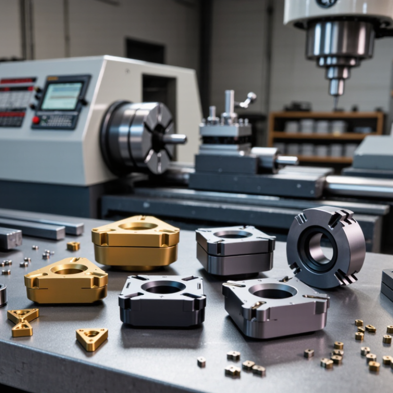
Choosing a carbide insert for hard alloy machining starts with the workpiece, not the insert catalog. Hard alloy may contain tungsten carbide, titanium carbide, or other abrasive phases. Its hardness, binder content, and surface condition strongly affect cutting behavior. A grade with high wear resistance often suits continuous cuts, while a tougher grade handles interrupted edges better.
Geometry matters just as much. A sharp cutting edge can reduce cutting force, but it may chip when the setup vibrates. A small edge hone improves strength, although it can increase heat and power demand. Positive rake geometry may help on thin sections. Negative geometry can survive heavier loads. Heat changes everything. Use stable cutting parameters, sufficient coolant when compatible, and rigid tool holding. Avoid forcing the insert through a work-hardened layer.
In practical trials, I inspect flank wear, edge chipping, and the machined surface after every short run. A dull gray wear land suggests abrasion; sudden notches may indicate excessive temperature or chemical wear. I record speed, feed, depth of cut, coolant flow, and workpiece hardness. This makes adjustment more reliable than relying on appearance alone. That choice is rarely perfect. Sometimes a tougher insert lasts longer, even when its nominal wear resistance looks lower. Carbide selection should reflect the actual cutting cycle, machine rigidity, and failure pattern, not only material hardness.
| Machining Condition | Typical Workpiece | Recommended Carbide Substrate | Typical Hardness | Coating Selection | Insert Geometry | Indicative Cutting Speed | Key Selection Reason |
|---|---|---|---|---|---|---|---|
| Interrupted roughing | Cast iron, forged steel, scale-covered surfaces | Tough, medium- to coarse-grained cemented carbide with approximately 8–15% cobalt binder | Typically below 300 HB for cast iron or below approximately 35 HRC for steel | Tough multilayer PVD or CVD coating; avoid excessively brittle high-hardness coatings during severe impact | Positive or reinforced negative geometry; large nose radius; strong cutting edge | Approximately 80–180 m/min, depending on material, insert grade, and depth of cut | Fracture resistance and edge strength are more important than maximum wear resistance |
| Continuous roughing | Low- and medium-carbon steel, alloy steel | Fine- to medium-grained carbide with approximately 6–12% cobalt binder | Approximately 150–300 HB | Wear-resistant multilayer coating, commonly based on titanium carbonitride, aluminium oxide, or titanium nitride layers | Negative rake for rigid setups; chipbreaker matched to feed and depth of cut | Approximately 120–250 m/min | Balances crater wear, flank wear, productivity, and edge stability |
| Finishing steel | Alloy steel, bearing steel, heat-treated steel below about 45 HRC | Fine-grained carbide with lower cobalt content, selected for high hardness and edge precision | Approximately 25–45 HRC | Smooth PVD or fine multilayer coating to reduce built-up edge and improve surface finish | Positive rake, sharp edge, small or medium nose radius; wiper geometry may improve finish on rigid machines | Approximately 150–300 m/min | A sharp, stable edge helps control cutting forces and dimensional variation |
| Hard turning | Hardened tool steel, bearing steel, die steel | Fine-grained carbide for moderate hardness; cubic boron nitride may be more suitable above approximately 45–55 HRC | Approximately 45–55 HRC when carbide is technically suitable | High-temperature-resistant PVD coating with a honed edge | Strong negative geometry; small depth of cut and controlled edge preparation | Approximately 60–150 m/min | Avoid carbide edge failure from excessive heat; use stable clamping and consistent engagement |
| Machining abrasive non-ferrous alloys | Aluminium-silicon alloy, copper alloy, brass | Fine-grained, high-hardness carbide with low tendency to form built-up edge | Material-dependent; aluminium-silicon alloys commonly range from about 80–150 HB | Polished, low-friction coating or uncoated polished carbide; avoid coatings that increase edge roughness | Highly positive rake, polished chip groove, sharp edge, and large clearance angle | Approximately 250–800 m/min, depending strongly on alloy and machine capability | Reduces built-up edge while resisting abrasive wear from silicon particles |
| Titanium and nickel-based superalloys | Titanium alloy, nickel-based heat-resistant alloy | Tough, fine- or medium-grained carbide with adequate cobalt binder and strong thermal-shock resistance | Usually approximately 30–45 HRC, but cutting difficulty is also affected by work hardening and low thermal conductivity | Sharp, adherent PVD coating designed for heat and adhesion resistance | Positive geometry, sharp but reinforced edge; avoid rubbing and excessive hone size | Approximately 20–80 m/min | Low cutting speed, continuous coolant where permitted, and stable feed help control heat and notching |
| High-speed milling of hardened alloy | Pre-hardened tool steel, mould steel, hardened alloy steel | Ultra-fine-grained carbide with high transverse-rupture strength | Approximately 35–50 HRC | Thin, hard PVD coating with good edge adhesion and low friction | Positive variable-pitch milling geometry; edge preparation matched to radial engagement | Approximately 80–250 m/min | Short tool overhang, balanced holders, and light radial engagement reduce vibration and chipping |
| Small-diameter drilling | Steel, cast iron, aluminium alloy, and general engineering alloys | Fine-grained carbide with high edge strength; grade must match the workpiece group | Workpiece-dependent | Wear-resistant PVD coating for steel; polished or low-friction surface for aluminium | Self-centering point, controlled margin width, and chip-splitting geometry for deep holes | Approximately 30–180 m/min, depending on diameter and material | Runout, coolant delivery, chip evacuation, and point geometry are as important as carbide grade |
Start with the workpiece, not the catalog. Check hardness, abrasive phases, binder content, and surface condition.
A wear-resistant grade often suits continuous cutting. A tougher grade usually handles interrupted edges better. Real results can differ.
A sharp edge lowers cutting force but may chip under vibration. A small edge hone improves strength and may increase heat.
Positive rake geometry can help thin sections. Negative geometry can survive heavier loads and rougher cutting conditions.
Inspect the flank wear land, edge, and machined surface after short runs. Record speed, feed, depth of cut, and coolant flow.
A dull gray wear land often suggests abrasion. Sudden notches may indicate excessive temperature or chemical wear. Inspect closely.
Use suitable geometry, stable holding, controlled runout, and effective chip evacuation. A smaller nose radius may improve detail.
Not always. Include insert usage, machine time, rejected parts, adjustments, and regrinding limits. One successful part proves little.
Test two or three geometries under identical conditions. Measure cutting time, wear width, roughness, and replacement frequency.
Review several batches, not one part. Check coolant delivery, machine rigidity, workholding, and workpiece hardness. Production is unpredictable.
Choosing the right Carbide Insert for Hard Alloy begins with understanding both the workpiece and the machining environment. Consider the alloy’s hardness, toughness, thermal behavior, and composition, as well as whether the operation involves roughing, finishing, interrupted cuts, or continuous turning. These factors guide the selection of insert grade, shape, clearance angle, chipbreaker, and cutting-edge preparation. A stronger edge may withstand demanding cuts, while a sharper geometry can improve precision and reduce cutting resistance during finishing work.
The insert coating should match the cutting temperature, wear conditions, and material being machined. Cutting speed, feed rate, and depth of cut must be adjusted together to maintain stability and prevent excessive heat, chipping, or built-up edge. Finally, evaluate performance through tool life, dimensional consistency, surface quality, and total machining cost rather than purchase price alone. A well-matched insert should provide reliable cutting, predictable replacement intervals, and efficient production across the intended application.